

The official technical recommendation for the pitches of the stadiums and training centres of the 2014 World Cup in Brazil specifies a drainage design in a “herringbone” pattern, with 4″ perforated HDPE pipes for the lateral drains and 6″ for the collector pipes. The same arrangement appears in DNIT’s Highway Drainage Manual, among the six devices provided for subsurface highway drainage. It is the most widely used layout in sports fields and in other areas that need fast runoff, and the intimidating name hides a simple logic. In this article you will understand what it is, how it works, when it makes sense to use it instead of the parallel system, and the installation details that determine whether the system will work or not.
What the herringbone drainage system is
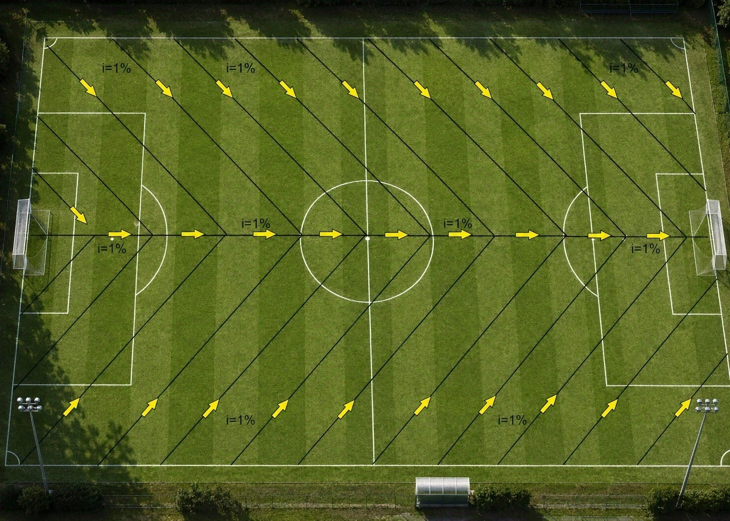
The name comes from its resemblance to the skeleton of a fish: a main collector pipe plays the role of the spine, and a series of lateral drains connected to it at an angle, the “bones”, cover the area to be drained. It is one of the three classic subsurface drainage arrangements, alongside the parallel system (straight, equally spaced lines) and the random system (used only on the wet spots of irregular terrain).
DNIT’s technical definition is straightforward: these are “drains intended for the drainage of large areas, paved or not, normally used in series, running obliquely in relation to the longitudinal axis of the highway or of the area to be drained”. The manual adds two characteristics that explain much of the arrangement’s popularity: they are generally shallow and, depending on ground conditions, they can discharge freely or into longitudinal drains.

How it works
The lateral drains, of smaller diameter, collect the water that has infiltrated the soil along the run and carry it to the central collector pipe, normally of larger diameter so as not to choke the system when the volume of several laterals converges into it. In drainage engineering literature, the formal difference between the two regular arrangements lies exactly there: in the parallel system the field drains reach the collector at a right angle, and in the herringbone system they reach it at an acute angle.
The real advantage of the arrangement is more concrete than is usually claimed. When the ground has a slope, placing the laterals at an angle allows the collector and the laterals to take advantage of the ground slope at the same time. In a parallel system with the collector running down the hillside, the field drains run practically along the contour lines and gain little slope of their own.
From this comes the practical consequence that matters most in a sports field. A study by Universidade Santa Cecília on the drainage of sports turf notes that the herringbone drain “manages to cover the entire area of the field and can also work at shallower depths”, while parallel drainage “also covers the whole field because it has longer drains, which requires a greater depth for its implementation”. Longer drains have to start deeper in order to keep the same slope all the way to the outlet. Less depth means less excavation, less volume of drainage material and less interference with the base of the turf.
The guide to building sand-based soccer fields from the state universities of the Pacific Northwest of the United States describes the same effect in very concrete terms: in the herringbone arrangement the field is split from the centre and the trenches are opened in each direction, which halves the length of each run of flow. A shorter run means water leaving the profile faster, which is exactly what you want in a field that has to be back in use soon after the rain.

The angle of the “bones” depends on the ground slope
This is the point that almost never appears in explanations of the arrangement, and it is what separates a design from a nice-looking drawing. The angle between the lateral drain and the axis of the area is not an aesthetic choice: it is a function of the ground slope. The USDA agricultural drainage manual describes exactly this mechanism when it says that the herringbone can be used when the collector runs in the direction of the main slope and “the desired grade of the lateral drains is obtained by varying the angle of junction with the collector”. In other words, the angle is the lever the designer uses to give each lateral the right grade. The IPR/DNIT training material for highway design provides the reference table, where α is the angle formed between the axis of the road and the axis of the “bone”, and L is the spacing between bones:
| Longitudinal slope (i%) | Drain angle α relative to the axis | Spacing L between drains |
|---|---|---|
| 0% | 90° | 4.00 m |
| 1% | 80° | 4.00 m |
| 2% | 70° | 4.00 m |
| 3% | 60° | 4.00 m |
| 4% | 50° | 6.00 m |
| 5% | 40° | 8.00 m |
| 6% | 30° | 10.00 m |
Source: IPR/DNIT, “Conceitos Básicos de Hidrologia e Drenagem para Projetos Rodoviários”, Module 6, Figure 3.12, adapted from JABÔR (2019). Original dimensions in centimetres.
Reading the table is a summary of the principle behind the arrangement. On flat ground the drain enters at 90°, that is, perpendicular, because there is no longitudinal slope to take advantage of and the only available grade comes from the cross section. As the slope increases, the angle closes, the drain starts running more aligned with the downhill direction and gains grade of its own. Since each drain now flows faster, it is able to serve a wider strip, and the spacing opens from 4 m to 10 m. On ground with a 6% slope, the same area is covered by less than half the number of drain lines. Each line becomes individually longer, because it crosses the area diagonally, so the gain shows up mainly in the number of trenches and junctions, not in the total length of pipe.
Herringbone vs. parallel system: when to use each
The parallel system is simpler to design and works well in large, flat, regular areas with uniform soil. The herringbone stands out in long, narrow areas, in irregular shapes, or where the slope is steeper. The comparison below brings together what the technical references point out on each side:
| Criterion | Herringbone | Parallel system |
|---|---|---|
| Connection of the laterals to the collector | Acute angle, usually on both sides | Right angle |
| Suitable terrain | Long and narrow areas, irregular shape, steeper slope | Flat, regular areas with uniform soil |
| Use of the available slope | Collector and laterals both take advantage of the slope | Mainly the collector |
| Required depth | Lower, because the runs are shorter | Greater, because longer drains require more depth |
| Installation and cost | More junctions, tends to cost more because of that | Fewer junctions, simpler to install |
| Point to watch | Double drainage occurs where two laterals reach the collector at the same point | Delivers little in irregular or narrow areas |
Sources: Illinois Drainage Guide (University of Illinois), Virginia Cooperative Extension (BSE-208), Cavelaars et al. (1994) and Pinto, Barbosa and Passos (UNISANTA, 2019).
It is worth recording the honest counterpoint, because it appears in those same sources: the herringbone tends to cost more than the parallel arrangement, because it involves more junctions, and it produces double drainage at the points where two opposite laterals meet the collector. This does not invalidate the arrangement, it just explains why it is not an automatic answer. In a large, flat, regular area, the parallel system delivers the same result for less. In practice, the decision depends on the shape and size of the area, the available slope, the expected volume of water and the outlet point, and there is no universal “best” between the two arrangements.
Spacing between drains: why there is no single number
This is the most common question and the one that causes the most execution errors. The spacing between drains is not a fixed table value: it is calculated using the Hooghoudt equation, which describes the drawdown of the water table between two drains as an ellipse and depends on the hydraulic conductivity of the soil, the maximum height of the water table above the drains and the design rainfall intensity.
Understanding the ellipse explains the most visible defect of a poorly spaced system. Between two drains, the water table does not fall in a straight line: it forms an arc, lower next to each drain and higher in the middle of the span. If the spacing is greater than the soil allows, the crest of that arc sits above the root zone, and that is what shows up at the surface as water accumulating in strips, always halfway between two drain lines.
A warning is due about a confusion that comes up a lot on site. In a sports field there are two different elements that are easily mistaken for one another: the drain lines, which are the trenches with pipe described above, and the sand grooves, shallow, narrow slits opened at the surface, transverse to the drain lines, to shorten the path the water travels to reach the drain. The two work at very different scales: in the system described by the PNW 675 guide, the drain lines are spaced every 15 feet, about 4.6 m, while the sand injection slits are 0.6 inch wide and spaced every 19 inches, something around 48 cm. Small spacings quoted in site conversations almost always refer to the grooves, not to the drain lines. Applying the number for one to the other leads to burying too much pipe and solving too little of the surface runoff.
Most common applications
The most frequent use of the herringbone is in sports fields and turf. See the complete guide to Beach Tennis court drainage, which details sizing, sand type and the geotextile required in that specific case. The same principle applies to soccer fields, multi-sport courts and other grass or sand areas that cannot be left with puddles of water.
Outside sports, the arrangement is standard in highway works. DNIT provides for herringbone drains in cuts where the longitudinal drains cannot handle the area, for ground that will receive fill with the water table close to the surface, and for embankments over impermeable natural soil. That is why the same drawing appears both in a turf field and in highway drainage, in railways and in airport aprons.
Installation considerations
- Spacing: defined by calculation based on the hydraulic conductivity of the soil, not copied from another project. Spacing greater than the soil can support leaves the water table high in the middle of the span, and that shows up as strips of water between the drain lines.
- Grade: the usual reference for sports turf is 1%, and the 2014 World Cup recommendation sets a minimum of 0.5% for levelling the bottom of the trenches. More important than the number is keeping the grade uniform along the whole run, with no counter-slope.
- Bedding: it has to be homogeneous, with no “bumps” under the pipe. Irregularities in the bed create low points where water stops, hamper flow and can damage the pipe depending on the sizing. The USGA specification requires that the excavated material be removed from the trench and that the bottom of the trench be smooth and clean, with the pipe laid on a gravel bed of at least 25 mm, precisely to guarantee positive grade along the entire length of the line.
- Collector diameter: undersizing the collector cancels out the rest of the design. In a soccer field case study, a 100 mm pipe delivered only half the required flow, and the design only worked out with a nominal diameter of 170 mm. The 2014 World Cup recommendation works with 4″ for the lateral drains and 6″ for the collector pipes.
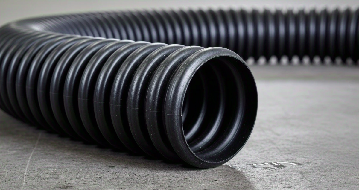
- Pipe material: HDPE (High-Density Polyethylene) is the indicated material because it is non-toxic, flexible, strong and durable. Techdreno is the line specific to this use, and Techdreno DW serves the runs that call for greater mechanical strength and higher flow, typical of a main collector under a trafficked area.
- Geotextile, and above all where it goes: the geotextile fabric (Bidim) filters the fine particles that would clog the pipe and physically separates the soil and sand layers. The detail that is usually done wrong is the position of the fabric. In sand-based sports construction, the two main references call for the geotextile as a barrier between the unstable subsoil and the drainage layer, and not as a sock wrapped around the pipe: the 2014 World Cup recommendation instructs placing the fabric on the sides and at the bottom of the trenches, without “wrapping” the assembly, and the USGA specification is even more direct, stating that under no circumstances should the fabric cover the pipes or the drainage trenches, and that pipes wrapped in fabric are not recommended in this type of work. In fine soil, in agricultural drainage and in highway works, on the other hand, wrapping the drain is common practice, because there the dominant risk is clogging by fines. In that scenario there is a more efficient alternative that does away with the fabric entirely: the Techdreno KC line has self-cleaning micro-slots that work as a passive filter, letting the fine grains through without clogging, solving the same risk the fabric would solve, without the cost and labour of wrapping the pipe. It is a design decision and it depends on the soil.
- Trench backfill: washed pea gravel or fine crushed stone around the pipe, the same material as the drainage layer. Where the space for excavation is restricted, the drainage geocomposite replaces part of the gravel section.
- Joints: a poorly sealed junction lets fine soil in and is where the system usually clogs first. The PNW 675 guide is explicit in requiring that all junctions be properly connected and taped shut, to prevent the entry of soil material and animals. Joints should be sealed, for example with Dutoseal Tape.
- Inspection boxes: the 2014 World Cup recommendation provides for inspection boxes for cleaning and assessing the system. A buried system with no inspection point only signals a problem once the turf has already flooded.
What drives the cost of the system
Adding up the figures already cited, the cost of herringbone drainage is governed by three decisions, and none of them is the brand of the pipe.
The first is the spacing, because it determines how many metres of pipe go into the area. The second is the available slope: according to the IPR/DNIT table, going from flat ground to a 6% slope allows the spacing to open from 4 m to 10 m, which halves the number of trenches and junctions needed to cover the same area. The third is the diameter: in the case study cited, adopting the diameter that effectively meets the design flow carried more than twice what was needed and, in the words of the study itself, if the hydraulic conductivity of the soil allowed it, it would be possible to “increase the spacing between drains, saving on material”.
That is why skimping on the collector diameter or tightening the grid “to be safe” usually ends up costing more. The lowest-cost path per square metre drained goes through testing the soil, taking advantage of the slope the ground already has, and sizing the collector for the actual flow. Techduto’s technical team assesses these three points together with your design before recommending a product line and diameter.
Frequently asked questions
Because the layout resembles the skeleton of a fish: the central collector pipe plays the role of the spine, and the lateral drains that connect to it at an angle represent the bones. In technical literature the arrangement appears as the “herringbone system”, and the formal definition is that the field drains reach the collector at an acute angle, and not at a right angle as in the parallel system.
It is not universally “better”, each one suits a different scenario. The herringbone stands out in long and narrow areas, in irregular shapes or with a steeper slope, because the collector and the laterals both take advantage of the slope and the system works at a shallower depth. The parallel system is simpler to design and install, has fewer junctions and works well in large, flat, regular areas. The herringbone tends to cost more precisely because of the larger number of junctions.
There is no single value: the spacing is calculated using the Hooghoudt equation and depends on the hydraulic conductivity of the soil, the height of the water table and the design rainfall. As an order of magnitude for shallow installation over a sand base, two independent specifications arrive at the same ceiling: the USGA sets a maximum of 15 feet (5 m) between lateral lines, and the technical recommendation for the 2014 World Cup stadiums uses 5 m between the trenches of the lateral drains. In highway drainage, the IPR/DNIT reference goes from 4 m on flat ground to 10 m at a 6% slope. Spacing greater than the soil allows leaves the water table high in the middle of the span, which shows up at the surface as water accumulating between the drain lines.
It is recommended. The geotextile (Bidim) filters the fine soil particles that would reach the pipe, preventing clogging, and physically separates the layers of material above and below the installation, which is especially important in sand courts over soil. How it is applied is a design decision: the technical recommendation for the 2014 World Cup stadiums, for example, instructs placing the fabric on the sides and at the bottom of the trenches, without wrapping the assembly.
References
- DNIT. Manual de Drenagem de Rodovias (Highway Drainage Manual), IPR-724, 2nd edition, 2006. Item 5.2 “Drenos em espinhas de peixe” (Herringbone drains). gov.br/dnit (PDF, in Portuguese)
- IPR/DNIT. Conceitos Básicos de Hidrologia e Drenagem para Projetos Rodoviários (Basic Concepts of Hydrology and Drainage for Highway Design), Module 6: Subsurface and deep drainage. Item 3.2 and Figure 3.12, adapted from JABÔR, M. A., Drenagem de Rodovias: Estudos Hidrológicos e Projetos de Drenagem, course notes, 2019. repositorio.enap.gov.br (PDF, in Portuguese)
- Brazilian 2014 World Cup Organizing Committee. Recomendação Técnica para Gramados em Estádios e CTs (Technical Recommendation for Turf in Stadiums and Training Centres), Rev. 0, 2009. PDF (in Portuguese)
- PINTO, M. G. S.; BARBOSA, R. R. P.; PASSOS, Y. M. Sistema de Drenagem de Gramados Esportivos (Drainage Systems for Sports Turf). Undergraduate final thesis, Civil Engineering, Universidade Santa Cecília (UNISANTA), Santos, 2019. cursos.unisanta.br (PDF, in Portuguese)